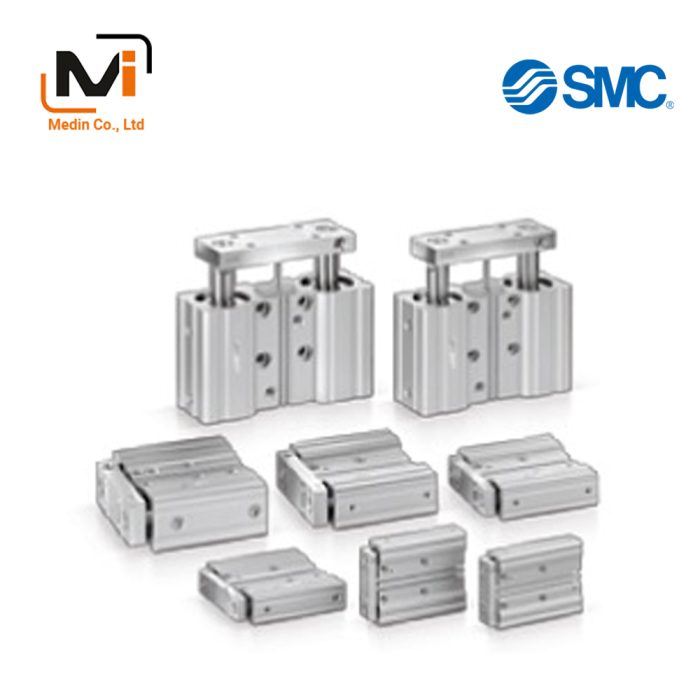
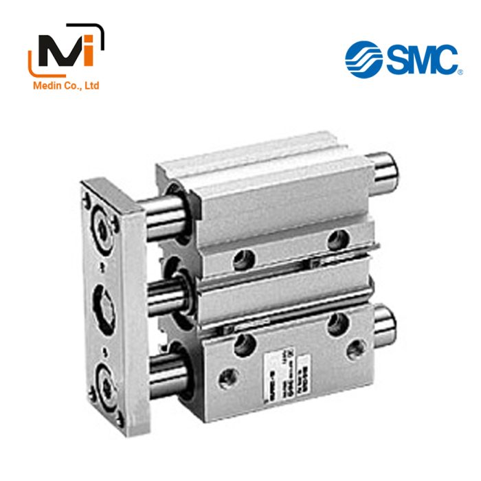
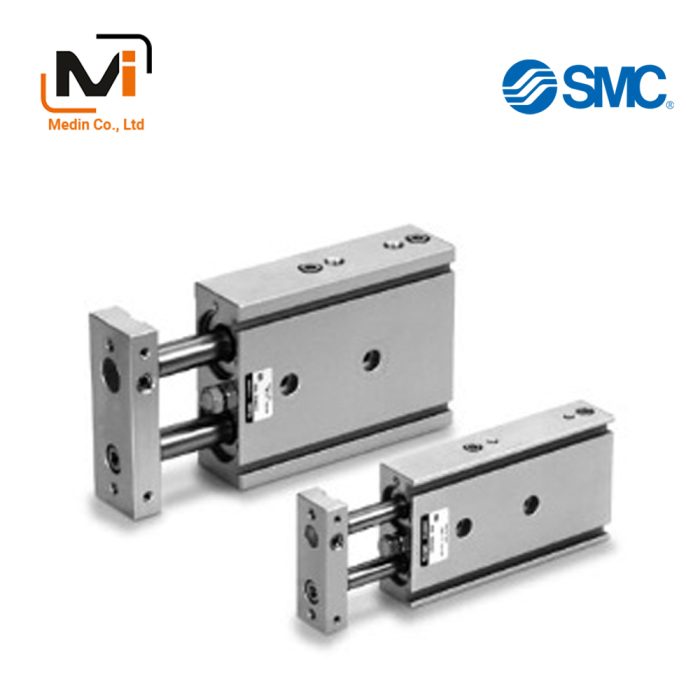
MLGP Series Low Profile Guide Cylinder With Lock – Xi Lanh Khí Nén SMC
Product Description
– Xi Lanh Khí Nén SMC
[Features]
· All strokes can be stopped at any position
Pressure drop and drop when exhausting residual pressure are prevented
· Weight is reduced by up to 17% by shortening the guide rod and changing the plate thickness
Guide rod shortened by up to 22 mm (Compared with conventional MLGPM)
· Compact auto switch and magnetic field resistant auto switch can be directly mounted on 2 sides
Download

– Xi Lanh Khí Nén SMC
Drawing
⌀20·⌀25·⌀32
T-groove
⌀40·⌀50·⌀63
T-groove
⌀80·⌀100
T-groove
Product Specifications
Part number display method
Cylinder specifications
| Tube inner diameter (mm) | 20 | 25 | 32 | 40 | 50 | 63 | 80 | 100 |
|---|---|---|---|---|---|---|---|---|
| Operating method | Double acting type | |||||||
| Operating fluid | Air | |||||||
| Guaranteed pressure resistant | 1.5 MPa | |||||||
| Maximum operating pressure | 1.0 MPa | |||||||
| Minimum operating pressure | 0.2 MPa^* | |||||||
| Ambient and fluid temperatures | -10°C to +60°C (no freezing) | |||||||
| Operating piston speed | 50 to 400 mm/s | |||||||
| Cushion | Rubber cushions on both sides | |||||||
| Lubrication | Not required (lubrication-free) | |||||||
| Stroke Length Tolerance | 0 to +1.5 mm | |||||||
| Piping connection port diameter (Rc, NPT, G) | 1/8 | 1/4 | 1/8 | |||||
*If the lock release air is not shared with the cylinder drive air, the minimum operating pressure is 0.15 MPa.
(The minimum operating pressure of the cylinder alone is 0.15 MPa.)
Lock specifications
| Tube inner diameter (mm) | 20 | 25 | 32 | 40 | 50 | 63 | 80 | 100 |
|---|---|---|---|---|---|---|---|---|
| Locking method | Spring locking (exhaust locking) | |||||||
| Unlocking pressure | 0.2 MPa or more | |||||||
| Locking Starting Pressure | 0.05 MPa or less | |||||||
| Locking Direction | One direction (extension locking, retraction locking) | |||||||
| Maximum operating pressure | 1.0 MPa | |||||||
| Unlocking piping connection port diameter (Rc, NPT, G) | M5 × 0.8 | 1/8 | 1/4 | |||||
| Holding power (maximum static load) (N)^* | 157 | 245 | 402 | 629 | 982 | 1,559 | 2,513 | 3,927 |
*The holding power (maximum static load) indicates the maximum capacity, not the normal holding capacity. Regarding the selection of the cylinder, please check the precautions and select the model.
* Please refer to the precautions for manually unlocking and holding the unlocked state.
Standard stroke table
| Tube inner diameter (mm) | Standard stroke (mm) |
|---|---|
| 20,25 | 20,30,40,50,75,100,125,150,175,200,250,300,350 |
| 32 to 80 | 25,50,75,100,125,150,175,200,250,300,350 |
| 100 | 50,75,100,125,150,175,200,250,300,350 |
Theoretical output table
| Tube inner diameter (mm) |
Rod diameter (mm) |
Operating Direction | Pressure receiving area (mm^2) |
Operating pressure (MPa) | ||||||||
|---|---|---|---|---|---|---|---|---|---|---|---|---|
| 0.2 | 0.3 | 0.4 | 0.5 | 0.6 | 0.7 | 0.8 | 0.9 | 1.0 | ||||
| 20 | 10 | OUT | 314 | 63 | 94 | 126 | 157 | 188 | 220 | 251 | 283 | 314 |
| IN | 236 | 47 | 71 | 94 | 118 | 142 | 165 | 189 | 212 | 236 | ||
| 25 | 12 | OUT | 491 | 98 | 147 | 196 | 246 | 295 | 344 | 393 | 442 | 491 |
| IN | 378 | 76 | 113 | 151 | 189 | 227 | 265 | 302 | 340 | 378 | ||
| 32 | 16 | OUT | 804 | 161 | 241 | 322 | 402 | 482 | 563 | 643 | 724 | 804 |
| IN | 603 | 121 | 181 | 241 | 302 | 362 | 422 | 482 | 543 | 603 | ||
| 40 | 16 | OUT | 1,257 | 251 | 377 | 503 | 629 | 754 | 880 | 1,006 | 1,131 | 1,257 |
| IN | 1,056 | 211 | 317 | 422 | 528 | 634 | 739 | 845 | 950 | 1,056 | ||
| 50 | 20 | OUT | 1,963 | 393 | 589 | 785 | 982 | 1,178 | 1,374 | 1,570 | 1,767 | 1,963 |
| IN | 1,649 | 330 | 495 | 660 | 825 | 990 | 1,154 | 1,319 | 1,484 | 1,649 | ||
| 63 | 20 | OUT | 3,117 | 623 | 935 | 1,247 | 1,559 | 1,870 | 2,182 | 2,494 | 2,805 | 3,117 |
| IN | 2,803 | 561 | 841 | 1,121 | 1,402 | 1,682 | 1,962 | 2,242 | 2,523 | 2,803 | ||
| 80 | 25 | OUT | 5,027 | 1,005 | 1,508 | 2,011 | 2,514 | 3,016 | 3,519 | 4,022 | 4,524 | 5,027 |
| IN | 4,536 | 907 | 1,361 | 1,814 | 2,268 | 2,722 | 3,175 | 3,629 | 4,082 | 4,536 | ||
| 100 | 30 | OUT | 7,854 | 1,571 | 2,356 | 3,142 | 3,927 | 4,712 | 5,498 | 6,283 | 7,069 | 7,854 |
| IN | 7,147 | 1,429 | 2,144 | 2,859 | 3,574 | 4,288 | 5,003 | 5,718 | 6,432 | 7,147 | ||
*Theoretical output (N) = pressure (MPa) × pressure receiving area (mm^2).
Standard table
⌀20·⌀25·⌀32
T-groove
| Tube inner diameter | a | b | c | d | e |
|---|---|---|---|---|---|
| 20 | 5.4 | 8.4 | 4.5 | 2.8 | 7.8 |
| 25 | 5.4 | 8.4 | 4.5 | 3 | 8.2 |
| 32 | 6.5 | 10.5 | 5.5 | 3.5 | 9.5 |
⌀40·⌀50·⌀63
T-groove
| Tube inner diameter | a | b | c | d | e |
|---|---|---|---|---|---|
| 40 | 6.5 | 10.5 | 5.5 | 4 | 11 |
| 50 | 8.5 | 13.5 | 7.5 | 4.5 | 13.5 |
| 63 | 11 | 17.8 | 10 | 7 | 18.5 |
⌀80·⌀100
T-groove
| Tube inner diameter | a | b | c | d | e |
|---|---|---|---|---|---|
| 80 | 13.3 | 20.3 | 12 | 8 | 22.5 |
| 100 | 15.3 | 23.3 | 13.5 | 10 | 30 |
Basic Information
| Rod Operation Method | Single Rods | Main Body Shape | Guided | Cylinder Operation Method | Double Acting |
|---|---|---|---|---|---|
| Additional Function | With Intermediate Stop Function | Environment, Applications | Standard | Cushion | Rubber bumper at both ends |
| Specification of cylinder | Compact guide cylinder with lock |
MLGPL20-75Z-B-M9BVL
MLGPL20-75Z-F
MLGPM20-20Z-B-M9NV
MLGPM20-20Z-F-M9BWL
MLGPM20-30Z-B-M9BVL
MLGPM20-30Z-F
MLGPM20-30Z-F-M9BAL
MLGPM20-30Z-F-M9BL
MLGPM20-30Z-F-M9BWL
MLGPL25-50Z-B
MLGPL25-50Z-F
MLGPL25-100Z-B
MLGPL25TF-20Z-B
MLGPM25-20Z-B
MLGPM25-30Z-B
MLGPM25-30Z-B-M9BW
MLGPM25-30Z-B-M9BWSDPC
MLGPM25-40Z-F
MLGPM25-50Z-B
MLGPM25-50Z-F
MLGPM25-50Z-F-M9BL
MLGPL40-50Z-F-M9BZ
MLGPL40-50Z-F-P3DWA
MLGPL40-100Z-F-M9BL
MLGPL40-125Z-B-M9BL
MLGPL40-125Z-F-M9BL
MLGPL40-150Z-F-M9BL
MLGPL40-175Z-B
MLGPL40-200Z-F
MLGPL40-300Z-F
MLGPL40-300Z-F-A90L
MLGPL50-50Z-F
MLGPL50-65Z-B-M9BL
MLGPL50-75Z-B-M9BL
MLGPL50-125Z-B
MLGPL50-125Z-B-M9BW
MLGPL50-125Z-B-M9BWSDPC
MLGPL50-150Z-F
MLGPL50-150Z-F-M9BW
MLGPL50TN-175Z-F
MLGPM50-25Z-B
MLGPM50-25Z-B-P3DWA
MLGPL63TN-100Z-B
MLGPL63TN-250Z-B
MLGPM63-25Z-F
MLGPM63-25Z-F-P3DWAZ
MLGPM63-50Z-B
MLGPM63-50Z-B-M9B
MLGPM63-50Z-B-M9BW
MLGPM63-50Z-B-M9BWL
MLGPM63-50Z-B-M9BWS
MLGPL80-50Z-B-M9BAL
MLGPL80-125Z-B-M9N
MLGPL80-200Z-B
MLGPL80-200Z-B-M9NW
MLGPL80-350Z-B-M9BW
MLGPL80TF-150Z-B
MLGPM80-50Z-B
MLGPM80-50Z-B-M9N
MLGPL100-300Z-B-A93
MLGPL100-350Z-B-M9BL
MLGPL100-350Z-B-M9BW
MLGPL100-350Z-B-M9BWL
MLGPL100-350Z-F-M9BL
MLGPM100-75Z-B
MLGPM100-75Z-F
MLGPM100-125Z-B
MLGPM100-150Z-F