HYG Series Hygienic Design Cylinder – Xi Lanh Khí Nén SMC
Product Description
– Xi Lanh Khí Nén SMC
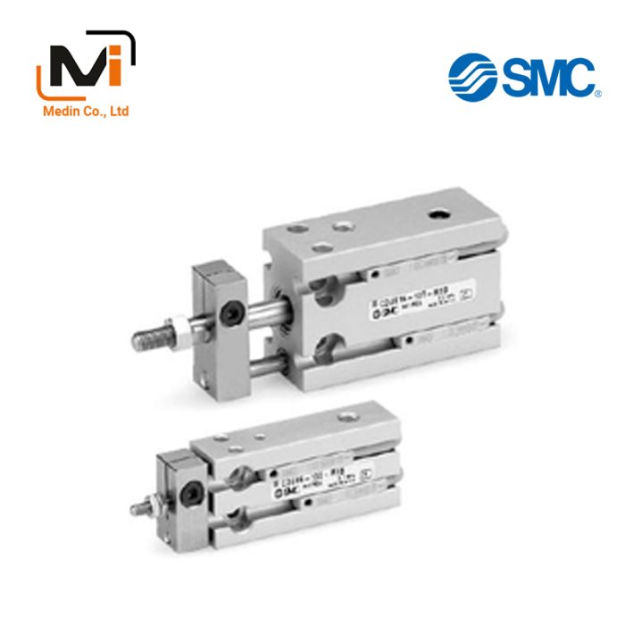
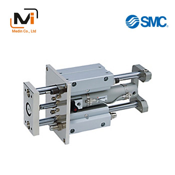
HYG Series Hygienic Design Cylinder with an easy-to-clean format.
[Features]
· Air cylinder with improved water resistance.
· To keep the product flat, grooves for auto switches and holes for cushion needles, etc. have been eliminated.
· Approximately 5 times increase in lifespan (compared to manufacturer’s current models).
· Able to handle food grease (NSF-H1 certified).
· NBR or FKM can be selected as the external sealant material.
· Mounting part: ISO standard (VDMA) compliant (HYC).
Download

HYG Series Hygienic Design Cylinder Details – Xi Lanh Khí Nén SMC

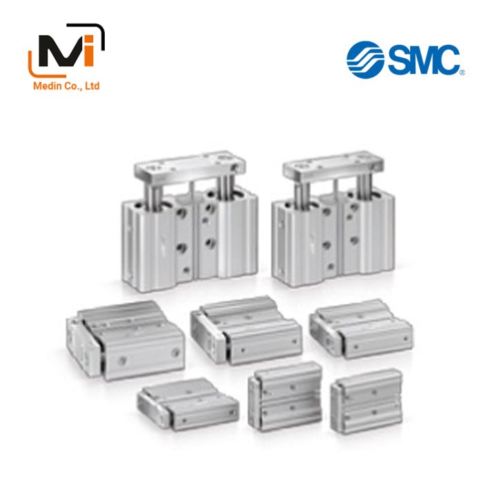
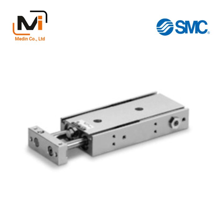
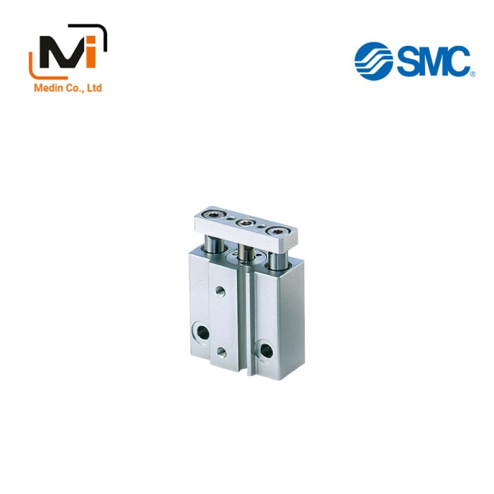
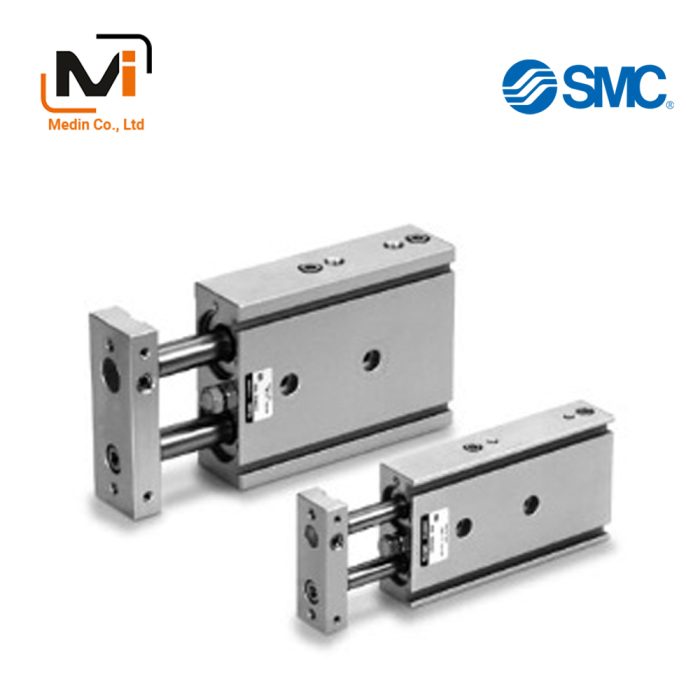
HYG Series Hygienic Design Cylinder product image
HYG Series Hygienic Design Cylinder Specifications
Model Number Notation
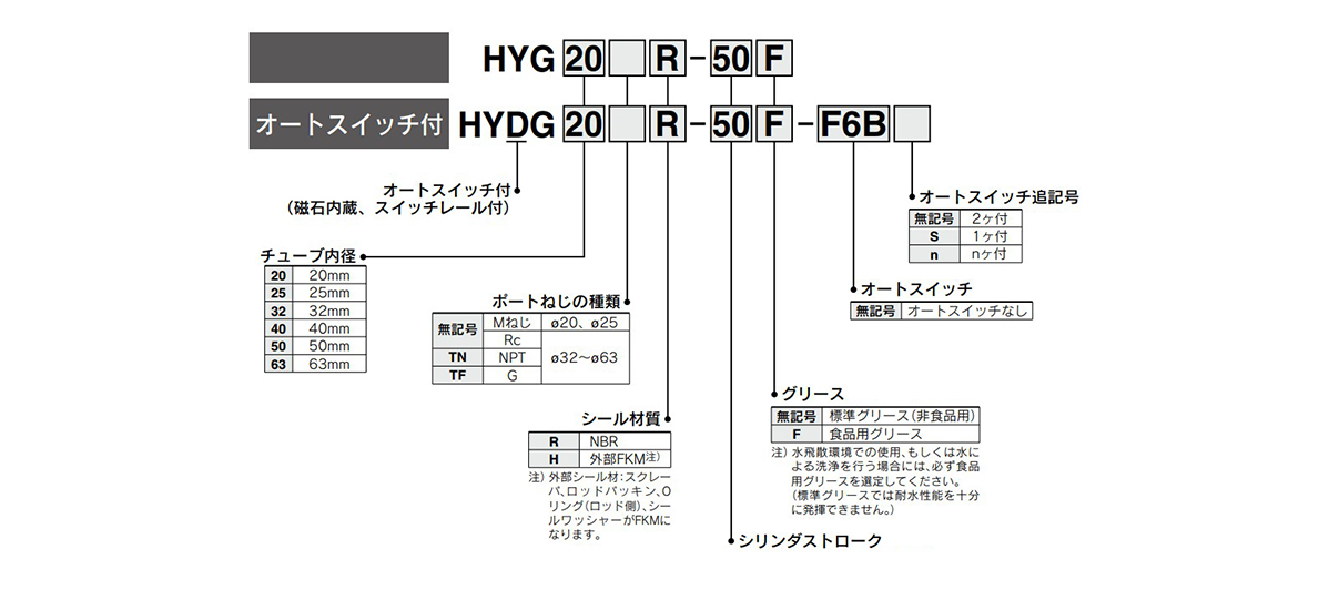
Model number examples
Specifications
| Tube Inner Diameter (mm) | 20 | 25 | 32 | 40 | 50 | 63 |
|---|---|---|---|---|---|---|
| Action | Double acting | |||||
| Fluid | Air | |||||
| Minimum operating pressure | 0.2 MPa | 0.15 MPa | ||||
| Maximum operating pressure | 1.0 MPa | |||||
| Proof Pressure | 1.5 MPa | |||||
| Ambient and Working Fluid Temperature | 0°C to 60°C | |||||
| Lubrication | Not required | |||||
| Piston Speed | 50 to 500 mm/s (with pressure at 1.0 MPa)* | |||||
| Cushioning | Rubber cushion | |||||
| Stroke length tolerance | (0 to +1.5) mm | |||||
*Use the product below the allowable kinetic energy.
Diagram
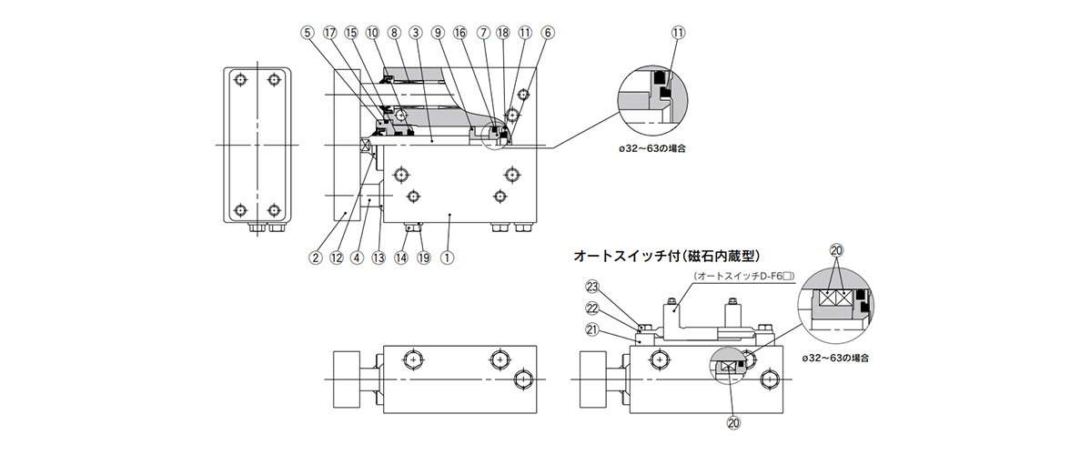
Diagram: HYG Series Hygienic Design Cylinder
Components
| Number | Part Name | Material | Quantity | Notes |
|---|---|---|---|---|
| 1 | Body | Aluminum alloy | 1 | Anodic oxide film |
| 2 | Plate | Aluminum alloy | 1 | Anodic oxide film |
| 3 | Piston rod | Stainless steel | 1 | Hard chrome plating |
| 4 | Guide rod | Stainless steel | 2 | Special coating |
| 5 | Rod cover | Aluminum alloy | 1 | Anodic oxide film |
| 6 | Head cover | Aluminum alloy | 1 | Chromate |
| 7 | Piston | Aluminum alloy | 1 | – |
| 8 | Bushing | Stainless steel | 4 | Special coating |
| 9 | Magnetic holder | Aluminum alloy | 1 | Chromate |
| 10 | Bumper A | Resin | 1 | – |
| 11 | Damper B | Resin | 1 | – |
| 12 | Scraper (piston rod) | Stainless steel + NBR | 1 | (FKM can be selected) |
| 13 | Scraper (guide rod) | Stainless steel + NBR | 2 | (FKM can be selected) |
| 14 | Port plug | Stainless steel | 3 | – |
| 15 | Rod packing | NBR | 1 | (FKM can be selected) |
| 16 | Piston packing | NBR | 1 | – |
| 17 | O-ring (rod end) | NBR | 1 | (FKM can be selected) |
| 18 | O-ring (head end) | NBR | 1 | – |
| 19 | Seal washer | Stainless steel + NBR | 3 | (FKM can be selected) |
| 20 | Magnet | – | 1 | (Only built-in magnet) (Over ø32 [32‑mm diameter]: 2 magnets) |
| 21 | Switch rail base | Stainless steel | 2 | (Only built-in magnet) |
| 22 | Switch rail | Stainless steel | 1 | (Only built-in magnet) |
| 23 | Hexagon bolt | Stainless steel | 2 | (Only built-in magnet) |
Replacement Parts / Seal Kit
| Tube inner diameter | Part No. | Set contents |
|---|---|---|
| 20 | HYG20□-PS | Set of (15), (16), (17), (19) listed above |
| 25 | HYG25□-PS | |
| 32 | HYG32□-PS |
- *Place the seal material symbol in □.
| Symbol | Material |
|---|---|
| R | NBR |
| H | External FKM* |
- *External seal: rod seal, O-ring (rod side) and seal washer are made from FKM.
- *Seal kit includes (15), (16), (17) and (19). Order the seal kit based on the bore size.
- *Since the seal kit does not include a grease pack, order it separately.
Grease package (food compatible grease): GR-H-010 (10 g)
Grease package (standard grease): GR-S-010 (10 g) - *To replace or repair seals of cylinder bore size 40 mm or greater, please contact the manufacturer with your request.
Please contact the manufacturer when the cylinder has to be disassembled for the purpose of replacing seals, etc.
HYG Series Hygienic Design Cylinder Example Dimensions

Dimensional drawings: without auto switch HYG20, 25
(Units: mm)
| Tube inner diameter | Standard Stroke | A | B | ||||||
|---|---|---|---|---|---|---|---|---|---|
| 30 st or less | 31 to 50 st | 51 to 100 st | 101 st or more | 30 st or less | 31 to 50 st | 51 to 100 st | 101 st or more | ||
| 20 | 20, 30, 50, 100, 150, 200 | 78.5 | 88.5 | 108.5 | 128.5 | 52 | 62 | 82 | 102 |
| 25 | 86 | 96 | 116 | 136 | 56.5 | 66.5 | 86.5 | 106.5 | |
(Units: mm)
| Tube inner diameter | C | D | E | F | G | H | J | K | L | MA | MB | N | P | PA |
|---|---|---|---|---|---|---|---|---|---|---|---|---|---|---|
| 20 | 36 | 83 | 14 | 30 | 81 | 18 | 54 | 12 | 10 | 4 | 27 | 12.5 | M5 × 0.8 | 16 |
| 25 | 42 | 93 | 16 | 38 | 91 | 21 | 64 | 16 | 12 | 4.5 | 32 | 13.5 | M5 × 0.8 | 18 |
(Units: mm)
| Tube inner diameter | PB | PC | PD | QA | QB | RA | RB | RC | RD | RE | RF | TA | TB | TC | TD | UA | UB | UC | UD |
|---|---|---|---|---|---|---|---|---|---|---|---|---|---|---|---|---|---|---|---|
| 20 | 32.5 | 14 | 28.5 | 7 | 68.5 | 39 | 9.5 | 32 | 5.4 | M6 × 1 | 12 | 24 | 72 | M5 × 0.8 | 13 | 18 | 70 | M5 × 0.8 | 10 |
| 25 | 34.5 | 15 | 34 | 8.5 | 78.5 | 41.5 | 9.5 | 38 | 5.4 | M6 × 1 | 12 | 29 | 80 | M6 × 1 | 14.5 | 26 | 78 | M6 × 1 | 12 |
- *The figure above shows the condition when shipped (top piping). Change the port plug position for side piping.
- *For more information on piping, refer to the specific product precautions.
Basic Information
| Cylinder Operation Method | Double Acting | Rod Operation Method | Single Rods | Main Body Shape | Guided |
|---|---|---|---|---|---|
| Additional Function | Standard | Environment, Applications | Standard | Cushion | Rubber cushion |
HYDG20H-10
HYDG20H-10-F6BLS
HYDG20H-10-F6BS
HYDG20H-10F
HYDG20H-10F-F6BLS
HYDG20H-10F-F6BS
HYDG20H-10F-F6BZS
HYDG20H-12
HYDG20H-12-F6BS
HYDG20H-15
HYDG25H-11
HYDG25H-11-F6BS
HYDG25H-20
HYDG25H-20-F6B
HYDG25H-20-F6BL
HYDG25H-20-F6BZ
HYDG25H-20-F6NZ
HYDG25H-20-F6P
HYDG25H-20F
HYDG25H-20F-F6B
HYDG25H-20F-F6BL
HYDG32H-15F-F6BZ
HYDG32H-20
HYDG32H-20F
HYDG32H-25
HYDG32H-25-F6B
HYDG32H-25-F6NL
HYDG32H-25F
HYDG32H-25F-F6B
HYDG32H-25F-F6BL
HYDG32H-25F-F6BS
HYDG32H-25F-F6BZ
HYDG32H-25F-F6NL
HYDG40H-15F-F6BL
HYDG40H-20
HYDG40H-25
HYDG40H-25-F6BL
HYDG40H-25-F6NZ
HYDG40H-25-F6P
HYDG40H-25F
HYDG40H-25F-F6B
HYDG40H-25F-F6BL
HYDG40H-25F-F6BS
HYDG40H-25F-F6NL
HYDG40H-25F-F6NZ
HYDG50H-25-F6BL
HYDG50H-25-F6BZ
HYDG50H-25F
HYDG50H-25F-F6BL
HYDG50H-25F-F6NL
HYDG50H-25F-F6PZ
HYDG50H-30-F6BLS
HYDG50H-40-F6BL
HYDG50H-50
HYDG50H-50-F6B
HYDG50H-50-F6BL
HYDG50H-50-F6BLS
HYDG63H-15F
HYDG63H-25-F6BZ
HYDG63H-25F-F6BL
HYDG63H-35F
HYDG63H-35F-F6B
HYDG63H-50
HYDG63H-50-F6BL
HYDG63H-50-F6BLS
HYDG63H-50F
HYDG63H-50F-F6BL
HYDG63H-50F-F6BLS
HYDG63H-50F-F6NLS