Parallel Type Air Gripper, 3-Finger Type, MHS3 Series – Xi Lanh Kẹp SMC
Product Description
– Xi Lanh Kẹp SMC
[Features]
· Lightweight and compact design with reduced height.
· High repeatability: ±0.01 mm.
· Can be equipped with an auto switch.
· Easy alignment when mounting the main body.
· Can be mounted from 2 directions.
· Utilizes wedge cam construction.
· Can be equipped with a small auto switch.
Download

Model Number Notation – Xi Lanh Kẹp SMC
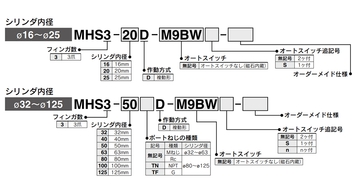
Model Number Notation
Features of MHS3 Series 3-Finger Type Parallel Type Air Chuck
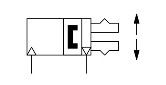
Double acting, inner-diameter grip JIS symbol
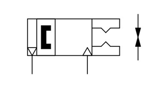
Double acting, outer-diameter grip JIS symbol
Specifications
| Model | MHS3-16D | MHS3-20D | MHS3-25D | MHS3-32D | MHS3-40D | MHS3-50D | MHS3-63D | MHS3-80D | MHS3-100D | MHS3-125D | |
|---|---|---|---|---|---|---|---|---|---|---|---|
| Cylinder inner diameter (mm) | 16 | 20 | 25 | 32 | 40 | 50 | 63 | 80 | 100 | 125 | |
| Applicable fluids | Air | ||||||||||
| Operating pressure (MPa) | 0.2 to 0.6 | 0.1 to 0.6 | |||||||||
| Ambient and fluid temperature (°C) | -10 to +60 | ||||||||||
| Repeatability (mm) | ±0.01 | ||||||||||
| Max. operating frequency (c.p.m.) | 120 | 60 | 30 | ||||||||
| Lubrication | Non-lube | ||||||||||
| Operating method | Double acting type | ||||||||||
| Effective gripping force (N)Note) at 0.5 MPa |
Outer-diameter grip power | 14 | 25 | 42 | 74 | 118 | 187 | 335 | 500 | 750 | 1,270 |
| Inner-diameter grip power | 16 | 28 | 47 | 82 | 130 | 204 | 359 | 525 | 780 | 1,320 | |
| Opening/closing stroke (mm) (diameter) | 4 | 4 | 6 | 8 | 8 | 12 | 16 | 20 | 24 | 32 | |
| Weight g | 60 | 100 | 140 | 237 | 351 | 541 | 992 | 1,850 | 3,340 | 6,460 | |
Note) Values for ø16 to 25 (cylinder inner diameter 16 to 25 mm) are with gripping point L = 20 mm, for ø32 to 63 (cylinder inner diameter 32 to 63 mm) with gripping point L = 30 mm, and for ø80 to 125 (cylinder inner diameter 80 to 125 mm) with gripping point L = 50 mm.
For the gripping force at each gripping location, refer to the data in “Effective Gripping Force” on pp. 587–589 in the manufacturer’s catalog.
Structural drawing
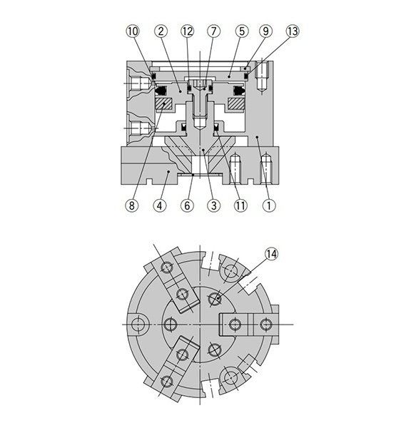
Closed condition structure drawing
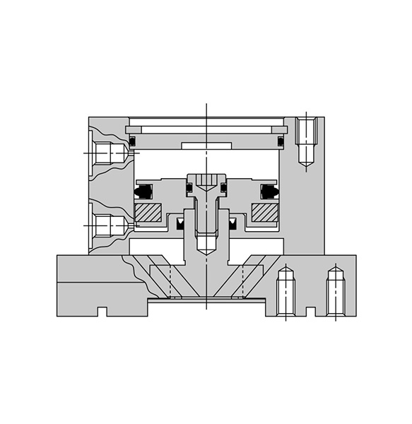
Open condition structure drawing
Component parts
| Number | Part name | Material | Note |
|---|---|---|---|
| 1 | Body | Aluminum Alloy | Hard anodizing |
| 2 | Piston | Aluminum Alloy | Hard anodizing |
| 3 | Cam | Carbon steel | Heat treated, specially treated |
| 4 | Finger | Carbon steel | Heat treated, specially treated |
| 5 | Cap | Aluminum Alloy | Hard anodizing |
| 6 | End plate | Stainless steel | – |
| 7 | Piston bolt | Stainless steel | – |
| 8 | Magnet | – | – |
| 9 | Type C retaining ring | Carbon steel | Phosphate coated |
| 10 | Piston Gasket | NBR | – |
| 11 | Rod Gasket | NBR | – |
| 12 | Gasket | NBR | – |
| 13 | Gasket | NBR | – |
| 14 | Cross-recessed flat-head screw | Carbon steel | Zinc chromate |
Replacement parts
| Part name | MHS3-16D | MHS3-20D | MHS3-25D | MHS3-32D | MHS3-40D | Principle parts |
|---|---|---|---|---|---|---|
| Gasket set | MHS16-PS | MHS20-PS | MHS25-PS | MHS32-PS | MHS40-PS | (10) (11) (12) (13) |
| Finger | P3316004 | P3316104 | P3316204 | P3316304 | P3316404 | (4) |
| Cam | P3316003 | P3316103 | P3316203 | P3316303 | P3316403 | (3) |
| Piston ass’y | MHS-A1601 | MHS-A2001 | MHS-A2501 | MHS-A3201 | MHS-A4001 | (2) (7) (8) |
| End plate ass’y | MHS-A1613-3 | MHS-A2013-3 | MHS-A2513-3 | MHS-A3213-3 | MHS-A4013-3 | (6) (14) |
| Cap | MHS-A16014 | MHS-A2014 | MHS-A2514 | MHS-A3214 | MHS-A4014 | (5) |
| Part name | MHS3-50D | MHS3-63D | MHS3-80D | MHS3-100D | MHS3-125D | Principle parts |
|---|---|---|---|---|---|---|
| Gasket set | MHS50-PS | MHS63-PS | MHS80-PS | MHS100-PS | MHS125-PS | (10) (11) (12) (13) |
| Finger | P3316504 | P3316604 | P3316704 | P3316804 | P3316904 | (4) |
| Cam | P3316503 | P3316603 | P3316703 | P3316803 | P3316903 | (3) |
| Piston ass’y | MHS-A5001 | MHS-A6301 | MHS-A8001 | MHS-A10001 | MHS-A12501 | (2) (7) (8) |
| End plate ass’y | MHS-A5013-3 | MHS-A6313-3 | MHS-A8013-3 | MHS-A10013-3 | MHS-A12513-3 | (6) (14) |
| Cap | MHS-A5014 | MHS-A6314 | MHS-A8014 | MHS-A10014 | MHS-A12514 | (5) |
- *Order 3 pieces per finger unit.
Replacement part / grease pack part number: MH-G01 (30 g)
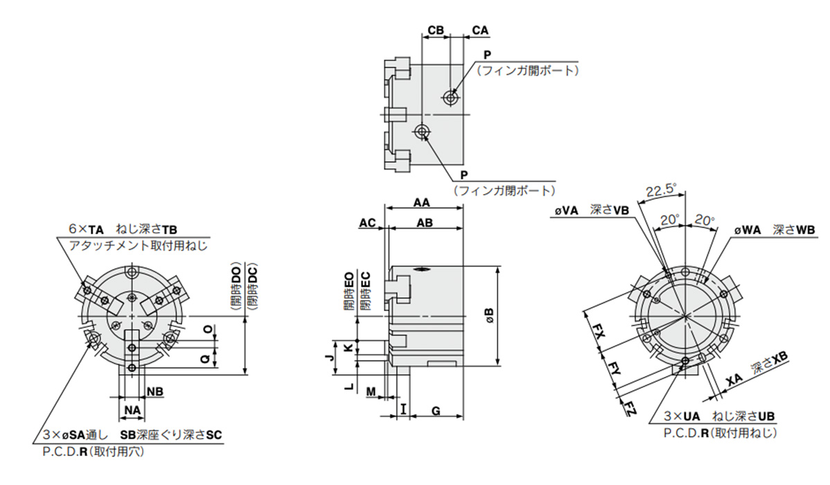
Outline dimensional drawing
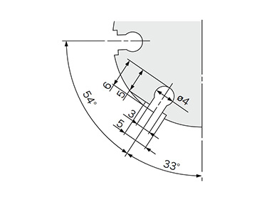
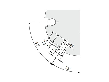
MHSJ3-16D to 25D
(Unit: mm)
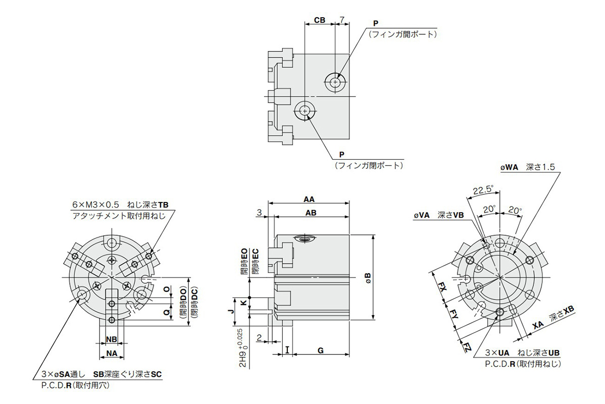
MHS3-16D to 25D external dimensional drawing
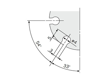
Auto Switch Mounting Groove (2 Locations)
(Unit: mm)
MHS3-16D
(Unit: mm)
MHS3-20D
(Unit: mm)
MHS3-25D
(Unit: mm)
| Model | AA | AB | B | CB | DC | DO | EC | EO | FX | FY | FZ | G | I | J | K | NA | NB | O | P | Q | R |
|---|---|---|---|---|---|---|---|---|---|---|---|---|---|---|---|---|---|---|---|---|---|
| MHS3-16D | 35 | 32 | 30 | 11 | 15 | 17 | 5 | 7 | 12.5 | 11 | 3 | 25 | 4 | 10 | 4 | 8 | 5h9 (-0.030 to 0) | 2 | M3 × 0.5 | 6 | 25 |
| MHS3-20D | 38 | 35 | 36 | 13 | 18 | 20 | 6 | 8 | 14.5 | 13 | 3 | 27 | 5 | 12 | 5 | 10 | 6h9 (-0.030 to 0) | 2.5 | M5 × 0.8 | 7 | 29 |
| MHS3-25D | 40 | 37 | 42 | 15 | 21 | 24 | 7 | 10 | 17 | 14.5 | 5 | 28 | 5 | 14 | 6 | 12 | 6h9 (-0.030 to 0) | 3 | M5 × 0.8 | 8 | 34 |
| Model | SA | SB | SC | TB | UA | UB | VA | VB | WA | XA | XB |
|---|---|---|---|---|---|---|---|---|---|---|---|
| MHS3-16D | 3.4 | 6.5 | 8 | 5 | M3 × 0.5 | 4.5 | 2H9 (0 to +0.025) | 2 | 17H9 (0 to +0.043) | 2H9 (0 to +0.025) | 2 |
| MHS3-20D | 3.4 | 6.5 | 9.5 | 6 | M3 × 0.5 | 6 | 2H9 (0 to +0.025) | 2 | 21H9 (0 to +0.052) | 2H9 (0 to +0.025) | 2 |
| MHS3-25D | 4.5 | 8 | 10 | 6 | M4 × 0.7 | 6 | 3H9 (0 to +0.025) | 3 | 26H9 (0 to +0.052) | 3H9 (0 to +0.025) | 3 |
MHSJ3-32D to 80D
(Unit: mm)
MHS3-32D to 80D external dimensional drawing
- *For other external dimensional drawings, usage, etc., refer to the manufacturer’s catalog.
Basic Information
| Type | Main body | Number of Fingers | 3 pcs. | Main Body Shape | Cylindrical Shape |
|---|---|---|---|---|---|
| Environment, Applications | Standard | Additional Functions | Not Provided |
MHS3-100D-M9B
MHS3-100D-M9B3
MHS3-100D-M9BA
MHS3-100D-M9BAL
MHS3-100D-M9BAL-X5
MHS3-100D-Y7BASBPC-X5
MHS3-125D
MHS3-125D-M9B
MHS3-125D-M9BA
MHS3-125D-M9BAL
MHS3-125D-M9BAL3-X5
MHS3-125D-M9BWZ
MHS3-16D
MHS3-16D-M9B
MHS3-16D-M9BA
MHS3-16D-M9BAL
MHS3-16D-M9BAL-X5
MHS3-16C-M9BM-X84
MHS3-16C-M9BVL-X84
MHS3-16C-M9BWS-X84
MHS3-16C-M9BWV-X84
MHS3-20D
MHS3-20D-M9B
MHS3-20D-M9B-X4
MHS3-20D-M9B-X5
MHS3-20D-M9BA
MHS3-20C-M9BVL-X84
MHS3-20D-M9NW
MHS3-20S-M9B-X84
MHS3-20S-M9BM-X84
MHS3-25D-M9B
MHS3-25D-M9B-X4
MHS3-25D-M9B-X5
MHS3-25D-M9B-X56
MHS3-25C-M9BL-X84
MHS3-25C-M9BWL-X84
MHS3-25C-M9NL-X84
MHS3-25C-M9NWVL-X84
MHS3-32D
MHS3-32D-M9B
MHS3-32D-M9B3
MHS3-32D-M9B-X4
MHS3-32D-M9BA
MHS3-32C-M9BS-X84
MHS3-32D-M9BAS
MHS3-32D-M9BASDPC-X56
MHS3-32D-M9BW-X5
MHS3-40D
MHS3-40D-M9B
MHS3-40D-M9B3
MHS3-40D-M9B-X56
MHS3-40D-M9BA
MHS3-40D-M9BA-X5
MHS3-40C-M9NM-X84
MHS3-40D-M9BASBPC3-X5
MHS3-40D-M9BASBPC-X5
MHS3-40D-M9BAVSBPC3-X5
MHS3-50D-M9B
MHS3-50D-M9B3
MHS3-50D-M9BA
MHS3-50D-M9BAL
MHS3-50D-M9BAL-X5
MHS3-50D-M9BALS
MHS3-50C-M9PWVSDPC3-X84
MHS3-50D-M9B-X4
MHS3-50D-M9BAVL-X5
MHS3-50D-M9BAVM3
MHS3-50D-M9BVM-X5
MHS3-63D
MHS3-63D-M9B
MHS3-63D-M9B3
MHS3-63D-M9BA
MHS3-63D-M9BA-X5
MHS3-63C-M9BL-X84
MHS3-63D-M9BASBPC3-X5
MHS3-63D-M9BAVSBPC
MHS3-80D
MHS3-80D-M9B
MHS3-80D-M9B3
MHS3-80D-M9B-X4
MHS3-80D-M9BAL3
MHS3-80D-M9BAVSBPCS
MHS3-80D-M9BAVZ
MHS3-80D-M9BSBPCS
MHS3-80D-M9BWVZ