Diaphragm Type Flow Switch IFW5 Series – Cảm Biến Áp Suất SMC
Product Description
– Cảm Biến Áp Suất SMC
A pressure switch made by SMC.
[Features]
· Low flow (1 L/min) setting is possible
· Easy to set
It can be set with a screwdriver from the outside without removing the cover
· With light
[Applications]
· Used for detection and confirmation of flow as a general-purpose water cutoff, water reduction relay in cooling water fixtures in general industrial machinery.
Download
Specifications of Diaphragm-Type Flow Switch IFW5 Series – Cảm Biến Áp Suất SMC

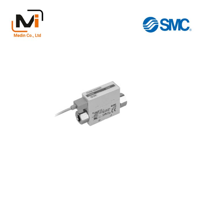
External appearance of IFW5 Series
| Fluid | Water / Non corrosive liquid* | |
|---|---|---|
| Operating Pressure | 0.1 to 0.6 MPa | |
| Water resistance | 1.2 MPa | |
| Operating temperature range | -5 to 60°C (no freezing) | |
| Action | Diaphragm Regulator | |
| Insulation Resistance | 100 MΩ or more (500 DC by insulation resistance tester) | |
| Withstand Voltage | 1,500 V AC for 1 minute | |
| Contact | Without terminal box: 1ab | |
| With terminal box: 1a and 1b | ||
| Connection port size | 3/8, 1/2, 3/4 | |
| Liquid-contacting parts material | Body | CAC408 |
| Rod | C3604B | |
| Diaphragm | *)NBR | |
* Please contact the manufacturer support center for further details of use.
*) Select “-X404” for ozone environment.
Model
| Model | Set flow rate range L/min | Maximum flow rate L/min | *) Hysteresis L/min |
|---|---|---|---|
| IFW510 | 1 to 10 | 20 | 1 or less |
| IFW520 | 10 to 20 | 25 | 1.5 or less |
| IFW550 | 20 to 50 | 60 | 3 or less |
*) Hysteresis is the flow rate required to move the micro switch from the operating position (ON signal) to the return position (OFF signal). (Typical value)
Microswitch rating
| Voltage | Non-inductive load (A) | Inductive load (A) | ||||||
|---|---|---|---|---|---|---|---|---|
| Load resistance | Lamp load | Inductive load | Electric motor load | |||||
| N.C. | N.O. | N.C. | N.O. | N.C. | N.O. | N.C. | N.O. | |
| AC125V | 5 | 5 | 1.5 | 0.7 | 4 | 4 | 2.5 | 1.3 |
| AC250V | 5 | 5 | 1 | 0.5 | 4 | 4 | 1.5 | 0.8 |
| DC8V | 7 | 5 | 3 | 3 | 5 | 4 | 3 | 3 |
| DC14V | 5 | 5 | 3 | 3 | 4 | 4 | 3 | 3 |
| DC30V | 5 | 5 | 3 | 3 | 4 | 4 | 3 | 3 |
| DC125V | 0.4 | 0.4 | 0.1 | 0.1 | 0.4 | 0.4 | 0.1 | 0.1 |
| DC250V | 0.3 | 0.3 | 0.05 | 0.05 | 0.3 | 0.3 | 0.05 | 0.05 |
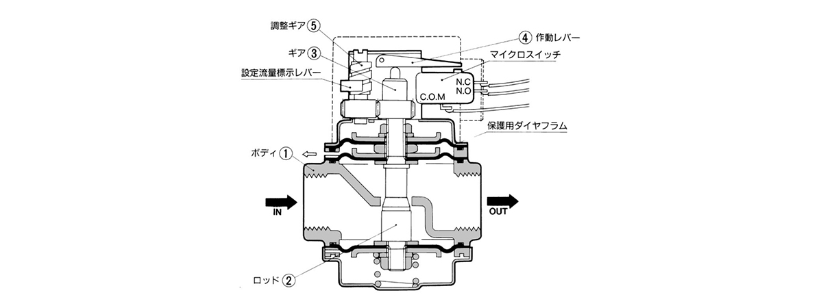
Structure and operating principle diagram

IFW5 Series structure and operating principle diagram
Operating Principle
When water flows, a differential pressure is generated before and after the orifice at the port of body 1. This differential pressure is detected by a pair of upper and lower diaphragms, rod 2 is displaced downward, operating lever 4 is lowered, and the micro switch is turned on.
If the flow rate is increased, the rod will be displaced downwards by 2, and if it is decreased, it will be displaced upwards. In addition, the adjustment gear 5 can be rotated and the gear 3 can be moved vertically to detect signals at any flow rate.
IFW510-03-00-Q
IFW510-03-01
IFW510-03-01-Q
IFW510-03-02
IFW510-03-03
IFW510-03-04
IFW510-03-10
IFW510-03-10-Q
IFW510-03-11
IFW510-03-11-Q
IFW510-03-12
IFW510-03-13
IFW510-03-13-Q
IFW510-03-14
IFW510-03-20
IFW510-03-20-Q
IFW510-03-21
IFW510-03-22
IFW510-03-23
IFW510-03-24
IFW510-03-55
IFW510-03-55-Q
IFW510-03-56
IFW510-03-56-Q
IFW510-03-65
IFW510-03-65-Q
IFW510-03-76
IFW510-03-76-Q
IFW510-03-85
IFW510-03-85-Q
IFW510-03-86
IFW510-03-86-Q
IFW510-04-00
IFW510-04-00-Q
IFW510-04-01
IFW510-04-01-Q
IFW510-04-02
IFW510-04-03
IFW510-04-04
IFW510-04-04-Q
IFW510-04-10
IFW510-04-10-Q
IFW510-04-11
IFW510-04-11-Q
IFW510-04-12
IFW510-04-12-Q
IFW510-04-13
IFW510-04-13-Q
IFW510-04-14
IFW510-04-20
IFW510-04-20-Q
IFW510-04-21
IFW510-04-22
IFW510-04-23
IFW510-04-24
IFW520-03-01
IFW520-03-02
IFW520-03-03
IFW520-03-04
IFW520-03-10
IFW520-03-10-Q
IFW520-03-11
IFW520-03-11-Q
IFW520-03-12
IFW520-03-13
IFW520-03-14
IFW520-03-20
IFW520-03-20-Q
IFW520-03-21
IFW520-03-22
IFW520-03-55
IFW520-03-56
IFW520-03-65
IFW520-03-66
IFW520-03-75
IFW520-03-76
IFW520-03-85
IFW520-03-86
IFW520-04-00
IFW520-04-00-Q
IFW520-04-01
IFW520-04-01-Q
IFW520-04-02
IFW520-04-03
IFW550-03-01
IFW550-03-02
IFW550-03-03
IFW550-03-10
IFW550-03-11
IFW550-03-12
IFW550-03-13
IFW550-03-14
IFW550-03-21
IFW550-03-22
IFW550-03-55
IFW550-03-56
IFW550-03-65
IFW550-03-66
IFW550-03-75
IFW550-03-76
IFW550-03-85
IFW550-03-86
IFW550-04-00
IFW550-04-00-Q
IFW550-04-01
IFW550-04-02
IFW550-04-03
IFW550-04-04
IFW550-04-10


