

Compact Cylinder, Standard Type, Single Acting, Single Rod CQS Series – Xi Lanh Khí Nén SMC
Product Description
– Xi Lanh Khí Nén SMC
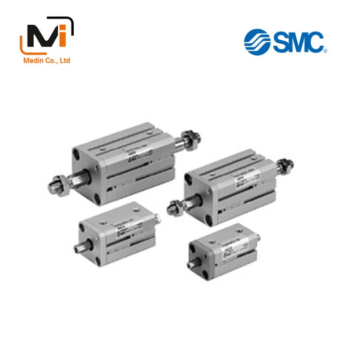
Compact Cylinder, Standard Type, Double Single, Single Rod CQS Series that allows 2-way basic mounting.
[Features]
· Ideal for machine designs with small space requirements.
· Square body shape that gives you flexibility for designing machines.
· Auto switch mounting direction allows for flexible design requirements.
· Non-rotating rod with high non-rotating accuracy.
Download

Compact Cylinder, Standard Type, Single Acting, Single Rod CQS Series Specifications – Xi Lanh Khí Nén SMC
Model Number Notation
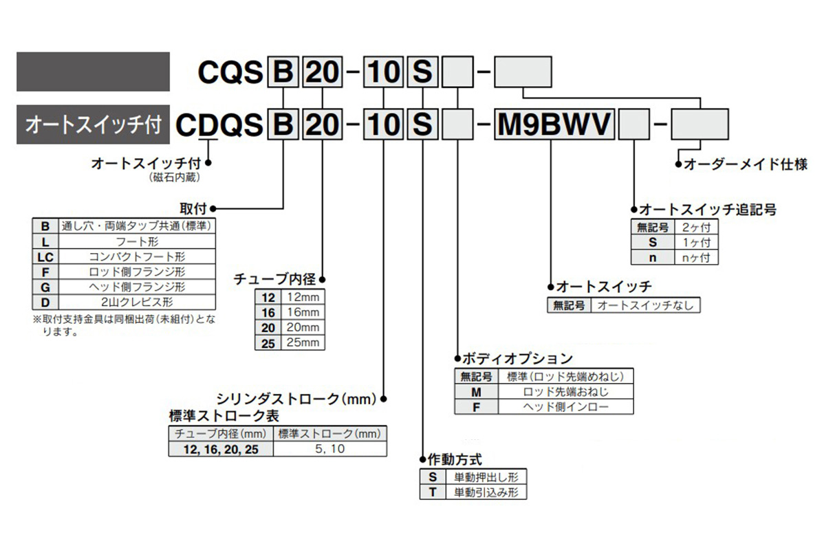
Model Number Notation
Standard specification
| Tube Internal Diameter (mm) | 12 | 16 | 20 | 25 |
|---|---|---|---|---|
| Operating method | Single acting, single rod | |||
| Applicable fluids | Air | |||
| Lubrication | Not required (non-lube) | |||
| Proof pressure | 1.5 MPa | |||
| Maximum operating pressure | 1.0 MPa | |||
| Minimum operating pressure | 0.25 MPa | 0.18 MPa | ||
| Ambient and working fluid temperature | Without auto switch: -10°C to 70°C (No freezing) | |||
| With auto switch: -10°C to 60°C (No freezing) | ||||
| Cushioning | None | |||
| Rod-end thread | Female thread | |||
| Stroke length tolerance | +1.0 mm 0 |
|||
| Operating piston speed | 50 to 500 mm/s | |||
| Allowable kinetic energy J | 0.022 | 0.038 | 0.055 | 0.09 |
Theoretical Output List
(N)
| Operating method | Bore size (mm) |
Rod diameter (mm) |
Operating Direction | Piston area (mm2) |
Operating pressure (MPa) | Retracted side | Extended side | ||
|---|---|---|---|---|---|---|---|---|---|
| 0.3 | 0.5 | 0.7 | |||||||
| Spring return | 12 | 6 | IN | – | 20 | 43 | 65 | 14 | 4 |
| OUT | 113 | ||||||||
| 16 | 8 | IN | – | 45 | 86 | 126 | 15 | 6 | |
| OUT | 201 | ||||||||
| 20 | 10 | IN | – | 78 | 141 | 204 | 15 | 6 | |
| OUT | 314 | ||||||||
| 25 | 12 | IN | – | 126 | 224 | 323 | 21 | 11 | |
| OUT | 491 | ||||||||
| Spring extend | 12 | 6 | IN | 84.8 | 14 | 31 | 48 | 10 | 3 |
| OUT | – | ||||||||
| 16 | 8 | IN | 151 | 24 | 54 | 85 | 19 | 4 | |
| OUT | – | ||||||||
| 20 | 10 | IN | 236 | 44 | 91 | 138 | 27 | 5 | |
| OUT | – | ||||||||
| 25 | 12 | IN | 378 | 84 | 160 | 235 | 29 | 10 | |
| OUT | – | ||||||||
Weight List / Without Auto Switch, Spring Return (Spring Extend)
(g)
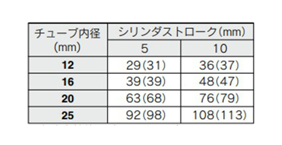
Weight List / Without Auto Switch, Spring Return (Spring Extend)
- *(): Denotes the values of spring extend.
Weight List / With Auto Switch (Built-In Magnet), Spring Return (Spring Extend)
(g)
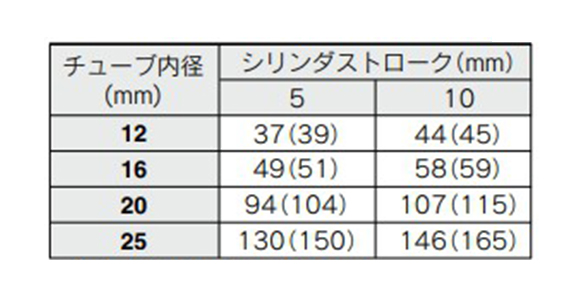
Weight List / With Auto Switch (Built-In Magnet), Spring Return (Spring Extend)
- *(): Denotes the values of spring extend.
Additional Weight List
(g)
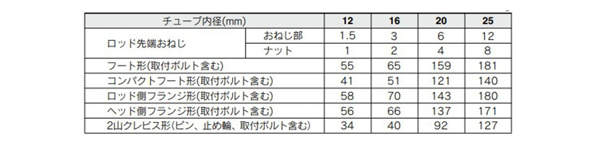
Additional Weight List
Structural drawing examples
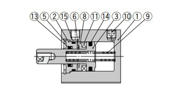
With auto switch (built-in magnet), single acting spring extend type: ø12 (12‑mm bore size) / ø16 (16‑mm bore size)
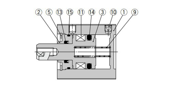
With auto switch (built-in magnet), single acting spring extend type: ø20 (20‑mm bore size) / ø25 (25‑mm bore size)
Component Parts
| Number | Part name | Material | Note |
|---|---|---|---|
| 1 | Cylinder tube | Aluminum Alloy | Hard Anodize |
| 2 | Collar | Aluminum Alloy | Anodized |
| 3 | Piston | Aluminum Alloy | Single acting, spring return |
| Stainless steel | Single acting, spring extend | ||
| 4 | Piston rod | Stainless steel | – |
| 5 | Retaining Ring | Carbon tool steel | Phosphate coated |
| 6 | Retaining Ring | Carbon tool steel | Nickel plating |
| 7 | Rod-end nut | Carbon steel | Zinc chromate |
| 8 | Spacer for switch type | Aluminum Alloy | Chromate |
| 9 | Return spring | Piano wire | Zinc chromate |
| 10 | Plug with fixed orifice | Alloy steel | Nickel plating |
| 11 | Magnet | – | – |
| 12 | Centering location ring | Aluminum Alloy | Anodized |
| 13 | Rod Gasket | NBR | – |
| 14 | Piston Gasket | NBR | – |
| 15 | Tube gasket | NBR | – |
Compact Cylinder, Standard Type, Single Acting, Single Rod CQS Series Dimensions

Standard type (through-hole / both ends tapped common): ø12 (12‑mm bore size) dimensional drawing
(Unit: mm)
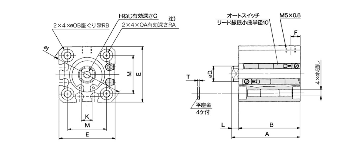
Standard type (through-hole / both ends tapped common): ø16 (16‑mm bore size) dimensional drawing

Standard type (through-hole / both ends tapped common): ø20/ø25 (20/25‑mm bore size) dimensional drawing
| Bore size (mm) |
Stroke range (mm) |
Without auto switch | With auto switch | C | D | E | F | H | I | K | L | M | N | OA | OB | RA | RB | T | ||||||
|---|---|---|---|---|---|---|---|---|---|---|---|---|---|---|---|---|---|---|---|---|---|---|---|---|
| A | B | A | B | |||||||||||||||||||||
| 5ST | 10ST | 5ST | 10ST | 5ST | 10ST | 5ST | 10ST | |||||||||||||||||
| 12 | 5, 10 | 25.5 | 30.5 | 22 | 27 | 30.5 | 35.5 | 27 | 32 | 6 | 6 | 25 | 5 | M3 × 0.5 | 32 | 5 | 3.5 | 15.5 | 3.5 | M4 × 0.7 | 6.5 | 7 | 4 | 0.5 |
| 16 | 25.5 | 30.5 | 22 | 27 | 30.5 | 35.5 | 27 | 32 | 8 | 8 | 29 | 5 | M4 × 0.7 | 38 | 6 | 3.5 | 20 | 3.5 | M4 × 0.7 | 6.5 | 7 | 4 | 0.5 | |
| 20 | 29 | 34 | 24.5 | 29.5 | 39 | 44 | 34.5 | 39.5 | 7 | 10 | 36 | 5.5 | M5 × 0.8 | 47 | 8 | 4.5 | 25.5 | 5.4 | M6 × 1.0 | 9 | 10 | 7 | 1 | |
| 25 | 32.5 | 37.5 | 27.5 | 32.5 | 42.5 | 47.5 | 37.5 | 42.5 | 12 | 12 | 40 | 5.5 | M6 × 1.0 | 52 | 10 | 5 | 28 | 5.4 | M6 × 1.0 | 9 | 10 | 7 | 1 | |
Note) For the following bore/stroke sizes, the through-hole is threaded: Standard type: ø12 (12‑mm bore size), ø16 (16‑mm bore size) 5 stroke.
Standard type: ø20 (20‑mm bore size), ø25 (25‑mm bore size) 5 and 10 stroke.
With auto switch and built-in magnet: ø20 (20‑mm bore size) 5 stroke.
Basic Information
| Rod Operation Method | Single Rods | Main Body Shape | Plate Cylinder | Additional Function | High rigidity / high precision high class guide |
|---|---|---|---|---|---|
| Environment, Applications | Standard | Cushion | None |
CDQSB12-5S-A90VLS
CDQSB16-5S-A90VLS
CDQSB20-5S-A93VLS
CDQSB25-5S-A93VLS